Currently you can only see the programmed (expected) traces like gradient or wavelength profiles. Acquisition of the signal and aux traces is planned for a future release of the Mobile Control.
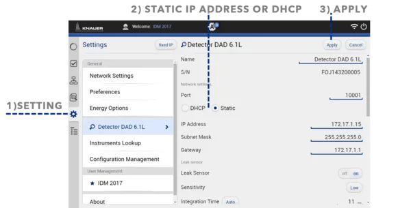
KNAUER devices are factory set to a dynamic IP address (DHCP). To ensure a permanent LAN connection between the chromatography software and the device set a fixed (static) IP address. A router is required to change LAN settings of all AZURA L devices and UVD 2.1S by Mobile Control.
Procedure in Mobile Control 1) Go to Settings and select device 2) Select Static or DHCP and For fixed IP address set IP address, Subnet mask and Gateway 3) Press Apply
Watch the video tutorial. The first part shows changing LAN settings by Mobile Control, the second part by Firmware Wizard.
Alternatively, the Firmware Wizard can be used to set a fixed IP address by direct LAN connection to selected devices.
There is a wide range of routers available with similar specifications but varying quality. From experience and testing we advise to use routers only recommended by KNAUER to avoid communication problems of your chromatography software. The intuitive user interface Mobile Control communicates with a router via WIFI or a USB-LAN adapter (not for use with a single device router). The software controls KNAUER devices or systems either remotely or locally.
For users who are using the mobile control app on a desktop PC or laptop, it is advisable to switch off the virtual keyboard to avoid having the virtual keyboard pop up every time they want to type something. The virtual keyboard is necessary to type with a tablet without real keyboard, but it is recommended to switch it off on a PC. Furthermore, with the virtual keyboard activated on a PC with a real keyboard, the user has to click on all buttons twice to get a reaction. The virtual keyboard can be switched off via System Settings > Preferences > Switch off ’’Show virtual keyboard’’. Please do not switch off the virtual keyboard, if you are using a tablet PC, as the Pop-up keyboard of your tablet will be switched off for all tablet applications.
The Mobile Control license is an excellent display solution for your KNAUER device or system.
The Mobile Control Chrom contains all functions and features of the Mobile Control, and furthermore offers the possibility to acquire and analyse chromatographic data.
Write an email to [email protected] and include at least the license code. It would be even better to provide contact data, customer number and invoice number as well for the request of a new delivery of the Mobile Control app. The replacement Mobile Control app is free of charge and can be ordered once.
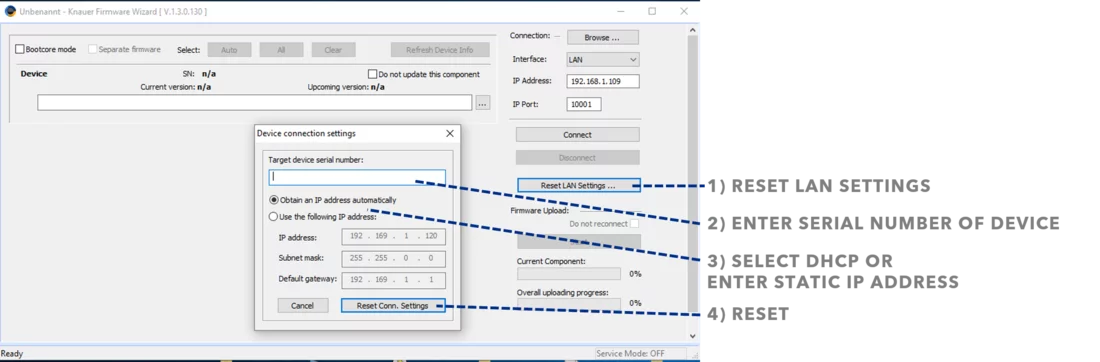
KNAUER devices are factory set to a dynamic IP address (DHCP). To ensure a permanent LAN connection between the chromatography software and the device set a fixed (static) IP address. The Firmware Wizard can be used to change LAN settings. If supported by your PC a direct LAN connection with selected devices can be used. Otherwise use a switch/router. Please find a list of AZURA devices with corresponding firmware versions below. Changing LAN settings does not work when the firmware wizard is connected to devices. Please disconnect before using this feature.
Procedure in Firmware Wizard 1) Select Reset LAN Settings 2) Enter the serial number of the AZURA device 3) Select fixed IP address (use following IP address) or DHCP (obtain an IP address automatically) For fixed IP address enter IP address, Subnet mask and Gateway. 4) Press Reset Communication Settings
Watch the video tutorial. The first part shows changing LAN settings by Mobile Control, the second part by Firmware Wizard (from 2:02 min).
Changing LAN settings with Firmware Wizard is supported for following devices/firmware versions.
Alternatively, Mobile Control can be used to change LAN settings.
Yes, it is possible to create, store, load and start the programs which include information for all devices. It is not yet possible to receive chromatograms.
Yes, every license is connected to one hardware device (tablet) via the MAC address of the hardware device. On the other hand, several HPLC systems can be operated via one tablet with different users at different times.
On some tablets the activation code is not accepted if the WLAN of your tablet is switched off. Switch on the WLAN and enter the activation code again. If the activation code is still not accepted, please contact the customer support at [email protected].
Lines and buttons shifted into each other can be a problem of your Android tablet settings. There are two settings that should be checked: 1) Settings > Display > Font size > should be set to ’’normal’’ 2) Settings > Accessibility > Large text > should be deactivated.
*) Current versions of Mobile Control only support Windows tablets.
You can send any device code generated by your tablet to KNAUER. The activation code you get will be valid for all of them, even if your tablet generated another device code during the licensing process.
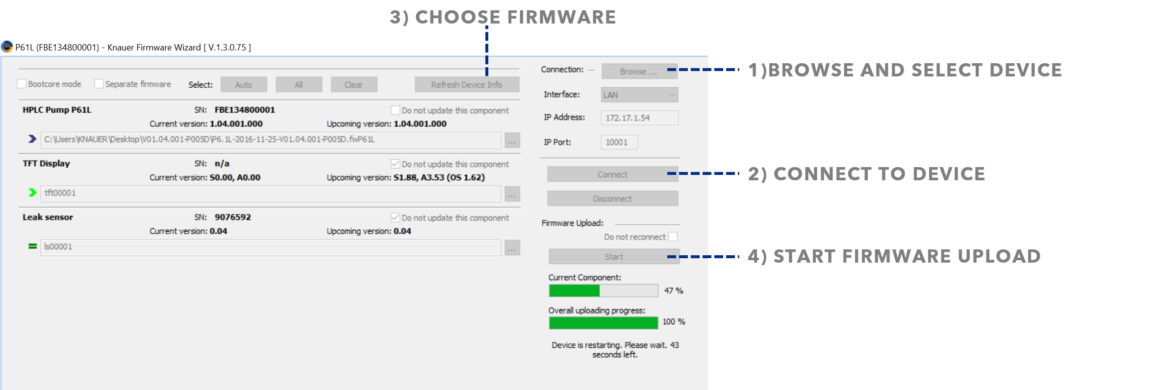
The firmware is the internal software of a device. Occasionally new firmware versions are released. The Firmware Wizard can be used to upload firmware on AZURA devices. Please note that the firmware is not included in the Firmware wizard.
Contact KNAUER Customer Support for a firmware update.
Procedure
Open Firmware Wizard
1) Browse and select a device 2) Connect to selected device 3) Choose the firmware package 4) Start firmware upload
click on image to enlarge
Firmware upload is supported for the following AZURA devices
RID 2.1L ASM 2.1L DAD 6.1L DAD 2.1L MWD 2.1L UVD 2.1L UVD 2.1S P 6.1L P 2.1L P 2.1S/P 4.1S CT 2.1
It is the pop-up keyboard necessary to type on tablets without a real keyboard.
Under Settings > Preferences you will find the option ’’Show virtual keyboard’’. This option only exists on the Windows version of the Mobile Control app*. For tablets without a physical keyboard: Please do not switch off the virtual keyboard. Switching it off leads to a deactivation of the pop-up keyboard for your tablet in general, not just for the mobile control. For PCs and laptops with a real keyboard: It is advisable to switch off the virtual keyboard. The virtual keyboard is not necessary for typing, if a real keyboard is present. Furthermore, on PCs with real keyboard activation of the virtual keyboard leads to having to click on all buttons twice to get a reaction.
*) Current Mobile Control versions don’t support Android tablets anymore, but Windows tablets exclusively.
2) You have the possibility to stop your pumps if you pause your run with the “Hold” button. Therefore check “Stop Pumps at Time Control Hold” in “Options”.
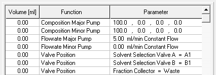
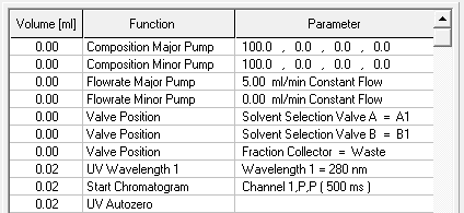
3) Start your method at time/volume point 0 with the function “Composition Major Pump” or “Composition Minor Pump” and with the Function “Flowrate”.
4) If you are using both pumps during the run, choose the composition and flow rate for both pumps at time point 0. You can choose a flowrate of 0 ml/min for the pump you want to start later.
5) Choose the default position of all your used valves at time point 0
6) Choose your wavelength (function “Wavelength”) and your required channels with the function “Start Chromatogram” from time point 0.02 (not 0.0).
7) Don’t forget to program an autozero.
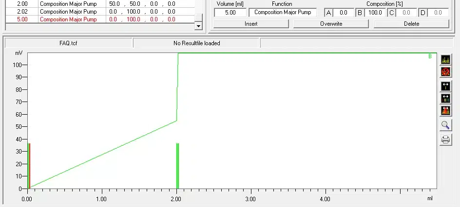
8) To program a gradient, you need to include all the angles of this gradient as compositions. A linear gradient will be calculated between two different compositions at two different time points. Program a small time difference between the compositions to create a step in your gradient. Using a P2.1L the smallest time difference should be 0.06 minutes.
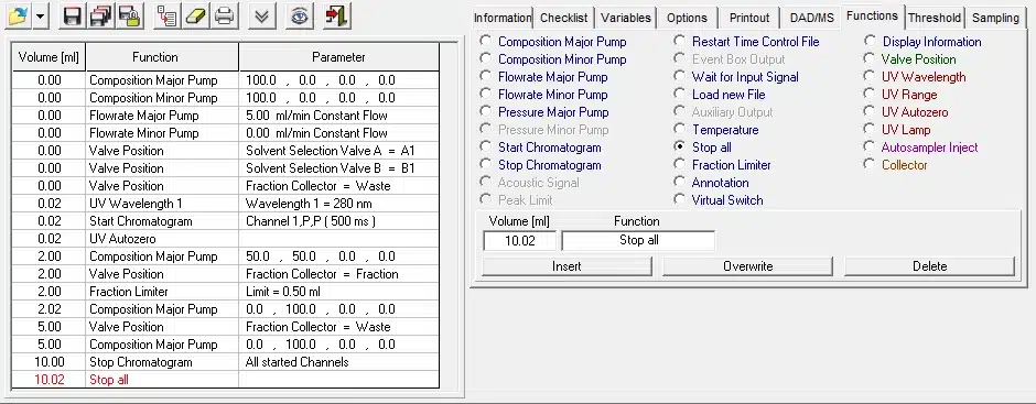
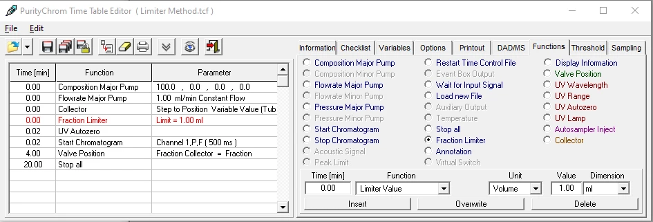
9) To start fractionation using a fraction collector, change the position of your fraction collector valve from “Waste” to “Fraction”. The function “Collector” enables you to move the collector arm to the wished position (“Step”: The arm will perform a step to the next position). Don’t program the function “Collector” at time point 0. To set a volume use the function “Fraction Limiter”. The current position of the fraction collector arm will be remembered until the program is switched off and on again.
10) To start fractionation using a fraction valve, change the position of your fraction valve from “Waste” to “Fraction”. You can choose a distinct position or the command “Next Step” to go automatically to the next position. To set a volume use the function “Fraction Limit”. The current position of the fraction valve will not be remembered by the software.
11) Program the function “Stop All” at the end of your method. The function “Stop Chromatogram” is only needed to if you want to restart your method automatically (function “Restart Time Control File”), if you want to link another method to your method (function “Load new File”) or if you are using your method in a sequence table.
Exemplary start conditions (Points 1 – 5)
Exemplary chromatogram definition (Points 6 – 7)
Exemplary gradient definition (Point 8)
Exemplary fractionation and stop commands (Points 9 – 11)
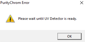
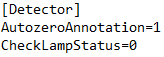
The error message “Please wait until UV Detector is ready” indicates that the lamp of the UV detector is off and thus, not ready for analysis. If you don´t want to receive this message, simply deactivate the checking of lamp status in the ini file. For that, open the file “PurityChrom.ini”, which you will find under C:Windows. In this file, please change under [Detector] the command “CheckLampStatus=0”. Now you should be able to open methods, although the UV lamp is not ready for running this method.
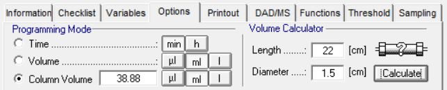
Create your methods in PurityChrom® based on column volume. In this way it is very easy to transfer your optimized methods if you are using differently sized columns. It is only necessary to adapt the volume of your column (see example in the left Figure). Columns of all vendors are supported in PurityChrom® and can be used with an AZURA FPLC.
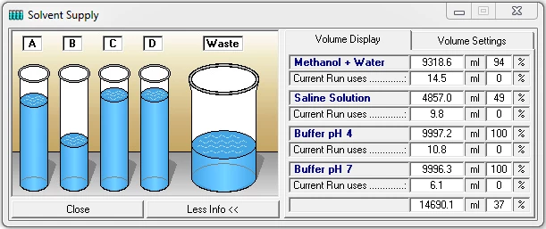
The function button or the menu option “Solvent Supply“ in the main window opens the solvent supply display window. You have the possibility of setting two volume limits in percent. When the volume drops below the first limit, an alarm will sound, and when it drops below the second limit, the pumps will stop. The values displayed are based on the calculated used volume of buffer at the current flow rate and time passed. Regular control of the supply containers helps to prevent a column from running dry.
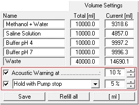
In the “Volume Settings’’ part, you can enter your own names for the buffers A to D under “Name”. Enter the total volume of the individual buffer containers in the boxes under “Total’’ and enter the current solvent volume in the containers under “Current”. The pumps should be stopped when you enter the current solvent volume, since the values in the boxes are constantly updated when the pumps are running, meaning that your entries will be overwritten. The “Refill All’’ button returns all the current solvent volumes to the total volume of the corresponding containers and the waste container to zero. The “Save’’ button applies and saves the settings. The option “Acoustic warning at’’ sets a percentage threshold at which the alarm will sound. The second threshold with the option “Stop all“ or “Hold with Pump stop“ is used to stop the pumps, in order to prevent the column from running dry. “Stop all“ stops the time control file and the pumps, and “Hold with Pump stop“ pauses the running of the time control file and sets the pumps to a flow rate of 0 ml. When the solvent containers have been refilled, you can resume the time control file using “Continue”.
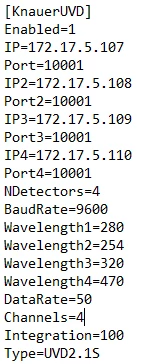
Yes, you can use up to four single wavelength detectors of one kind (UVD2.1S, UVD2.1L) with the PurityChrom software! To do this please keep in mind, that all UV-detectors need to communicate via a unique fixed IP address. The configuration is carried out in the PurityChrom.ini file as shown examplary on the left.
PurityChrom.ini entry for multiple single wavelength detectors
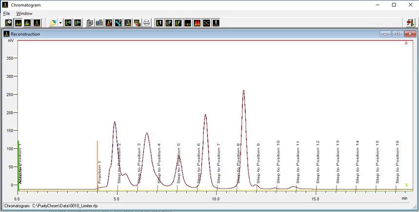
Fractionation via a limiter is often used in standard FPLC runs. It means, that upon setting the fraction collector into fractionation mode, it will collect the same size fractions as long as it is in this mode. An example of the fractionation behavior you can see pictured. You see here that the same volume is collected for each fraction unless you interfere with the fractionation manually. This is convenient especially for runs with less defined peak shapes, low UV intensities and to make sure, that no material is lost during the run. However, the possibility of contaminating the product of interest is likely because no active surveillance of UV signal is involved in this fractionation type, as you can see in the exemplary run for fraction 8.
To implement the limiter in a method, you add the command “Fraction Limiter” and define the volume which is repeatedly collected during the run. In this example, the tube is changed after a volume of 1 ml is collected. The fractionation is started by switching the fraction collector valve into the fractionation position at the point of your choice.
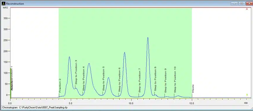
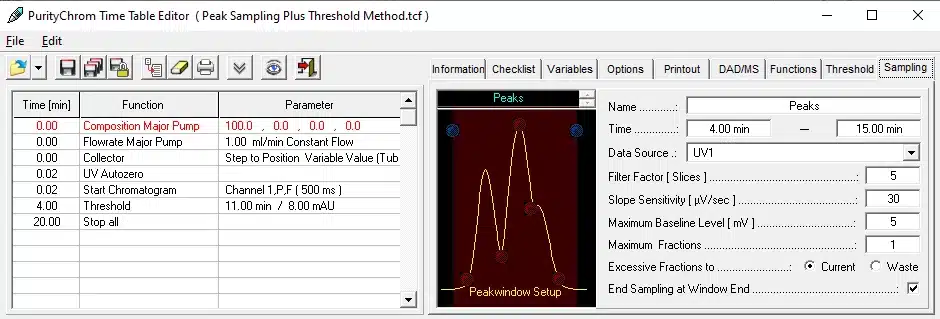
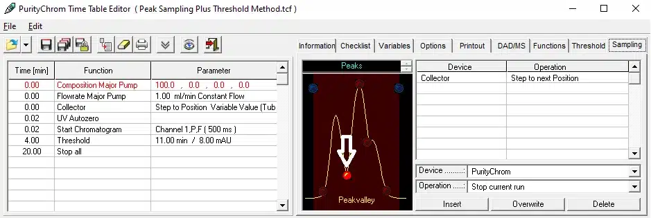
You can fractionate peaks using the automated peak sampling in PurityChrom. In this mode the peaks of your run are analyzed by several factors like slope and baseline and a customizable fractionation is carried out while the peak situation (e.g. peak start, peak valley, peak maximum, peak shoulder and peak end) is determined
In the time control file, you can find the tab “sampling”. Here one defines the time range in which the automatic fractionation should be active. Also, you can define which data source is used for the peak sampling and how many data points are averaged over (“filter factor”). The value for “slope sensitivity” is the most important point, because here a new peak can be identified by its steepness. The “maximum baseline level” is the value, which determines whether a peak valley or a peak end is identified. You must put in a value higher than the usual baseline of the chromatogram you want to fractionate. The settings under “maximum fractions” and “excessive fractions to” are used with specialized valves but do not apply to KNAUER hardware.
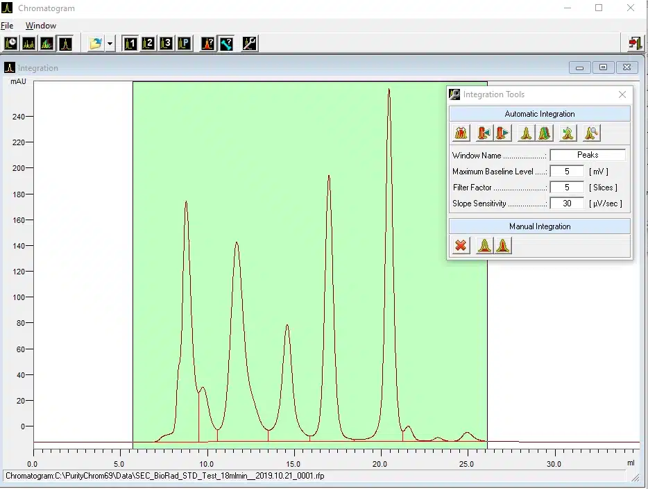
To define which actions are taken at which peak situation you click on the dot of the peak situation and then define the actions, that should be carried out by the software. To get a rough idea of the values “maximum baseline level”, “filter factor” and “slope sensitivity”, which are compatible with the peak situation of your chromatogram you can use the integration function in PurityChrom.
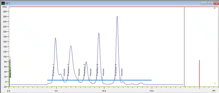
PurityChrom gives you the possibility to fractionate peaks via thresholds. This is an optimal fractionation method for well baseline separated and defined peaks. A threshold is set at a specific UV Level as indicated in the example by the blue line. If a signal is overstepping this value, fractionation will be automatically started. If the signal falls below the threshold, fractionation will be stopped, and the valve will switch back to waste position. Both levels can also differ. Be aware that if a peak also consists of a shoulder, which is above the threshold, this shoulder will be collected in the same fraction.
You can also combine the limiter with a threshold. Every fraction, that is recognized by the threshold settings, will be divided into smaller sub-fractions by the limiter function and thus, fractions will not be bigger than the defined limiter value. If you adjust the limiter volume according to your working flowrate and regular fraction sizes, you will minimize contaminations by peak shoulders.
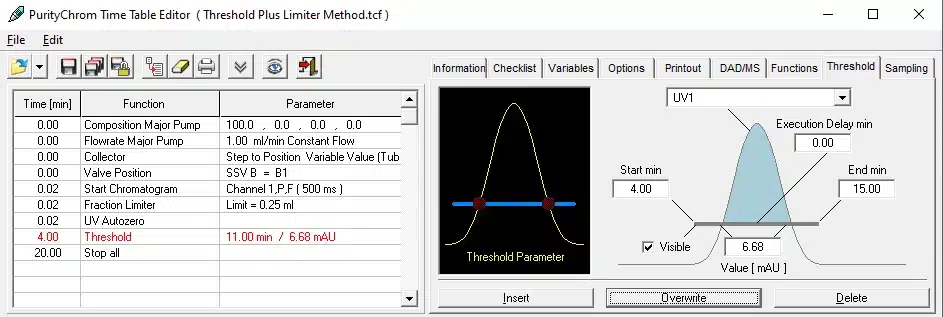
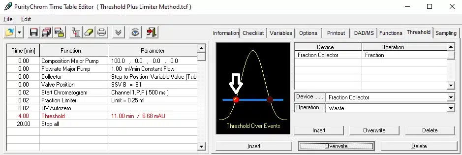
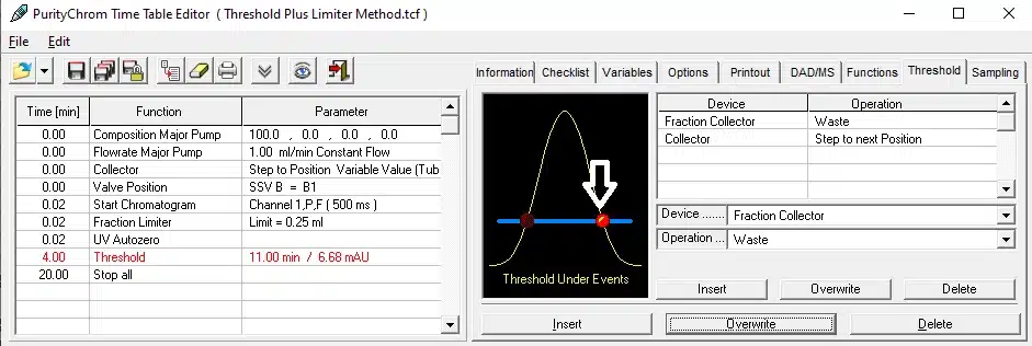
The fractionation via threshold can be defined in a method (time control file) using the threshold tab. Here you can specify at which start and end point the threshold function should be active and which level of signal is triggering the threshold actions. It is important to define the actions that should be carried out upon exceeding or undershooting the signal. This you can do by clicking on the red dots indicated in the screenshots. After defining all parameters for the threshold function, don´t forget to insert them into your time control file by using the button “insert”.
If you want to have different UV values for start and end point of your fraction collection, simply add two thresholds with different UV signal intensities and then define for one only the “Over Event actions” and for the other only the “Under Event actions”. When you would like to combine the limiter and the threshold, simply add the “fraction limiter” command to your method.
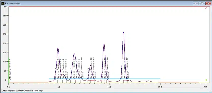
Chromatogram with a fractionation via a threshold
Chromatogram with a fractionation via a threshold plus limiter
Writing a method with a fractionation via threshold
Defining the actions when UV signal threshold is exceeded
Defining the actions when UV signal falls below the threshold
The software always shows an error, that no license is available. The OpenLAB Control Panel shows a valid license. Before adding the license, the software runs well with the 60-day startup license.
There are 4 known causes, why this may happen:
1. For OpenLAB CDS EZChrom Edition A.02.01/A.04.06 at least Update 1 must be installed; otherwise the license will not been recognized. Check the KNAUER OpenLAB driver installation disk, the required update can be found there.
2. If you create a license in your SubscribeNet account for a workstation installation, you must not enter the computer name in the corresponding form. Either leave this field empty (recommended by KNAUER) or only enter localhost as name. If any other name will be entered, the license will not work. Unfortunately, this information is missing on the licensing webpage.
3. The OpenLAB license is bound to the MAC address of a network adapter of the computer. If your computer is equipped with more than one network adapter (more than one network card, wireless LAN, cellular phone network), OpenLAB may not show the correct MAC address. The license permanently only works, if it is created for the MAC address of the network card for the chromatographic system. KNAUER recommends to check the available network adapters in the Windows Control Panel > Network and Internet > Network and Sharing Center; there click on the link Change adapter settings on the left side. All of the installed network adapters will be shown. In the properties of a network adapter the MAC address will be shown.
4. In very rare cases the Agilent OpenLAB Instrument Server is stopped. This service is necessary for opening an instrument. To check if the service runs, open the Windows Task Manager, select the tab “Services” and click on the button <Services…> in the bottom of the window. In the list of available services check, if the status of the service Agilent OpenLAB Instrument Server is on “Started”. If not, start it; the Startup type should be set on “Automatic”.
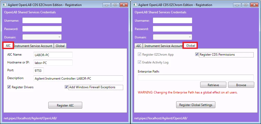
In OpenLAB CDS EZChrom Edition an instrument is linked to the computer name of the AIC (Agilent Instrument Controller). For workstations, the instrument controller name will be filled automatically, if an instrument is created and cannot be changed later on. If the computer name is changed, the instrument will not work anymore, because the software cannot connect to the mentioned computer. When the OpenLAB EE computer is integrated into a company’s network, normally the administrator will change the computer name. Finally, existing instruments cannot be used with the renamed computer.
Two steps need to be followed to make OpenLAB EE running again:
1. The computer must be registered in the software with its new name. Open the “AIC and Driver Install Tool” from Start > programs > Agilent Technologies > OpenLAB CDS EZChrom Edition. Run the registration from tabs “AIC” and “Global”.
2. Create a new instrument; the correct instrument controller name will be added automatically.
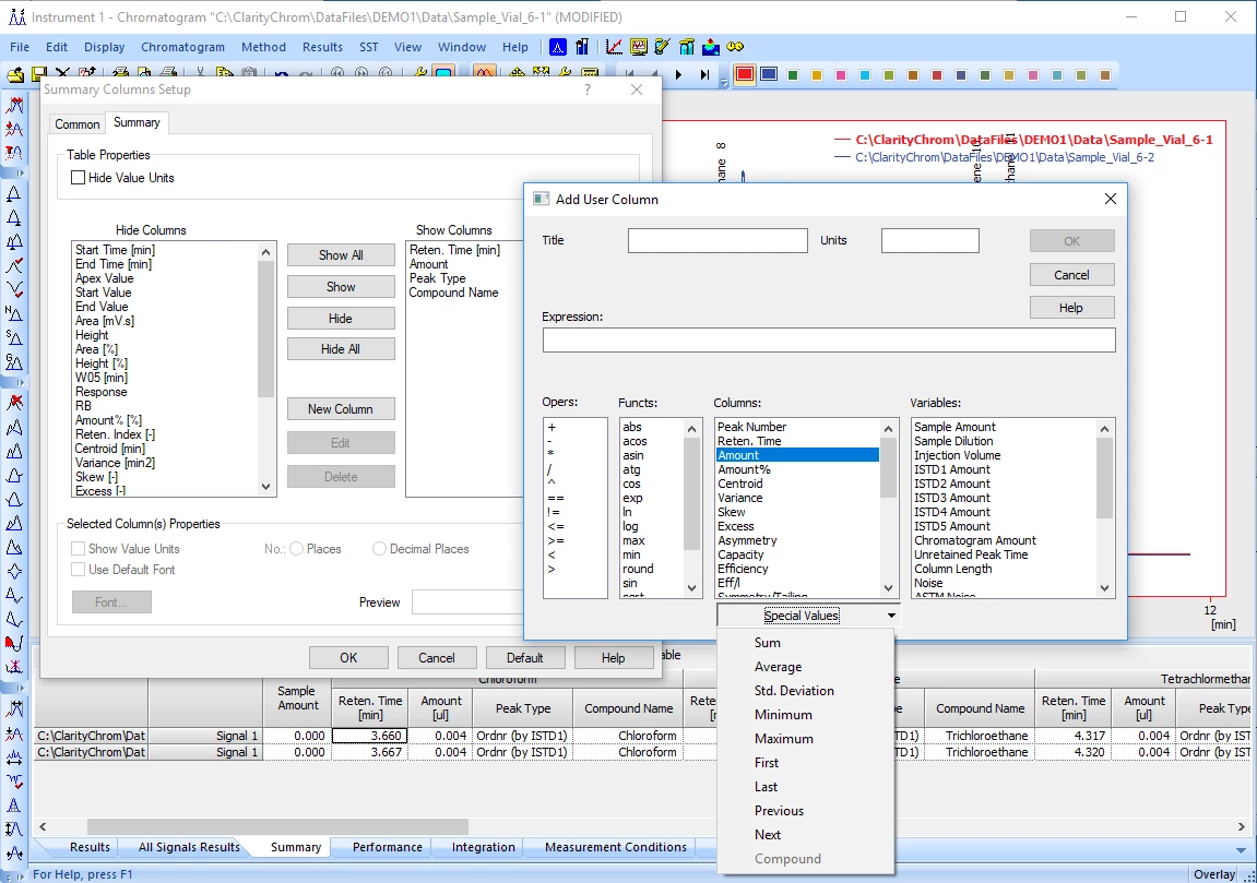
Yes, it is possible to calculate %RSD in Summary table without a SST license. ClarityChrom includes the cool feature of “User Columns”, which allows a wide variety of calculations, based on the results in the chromatograms.
1. Overlay all chromatograms in the chromatogram window, which should be included in the calculation.
2. Make sure all chromatograms have been analyzed. Only identified (calibrated) peaks will be used for calculation.
3. Select the “Summary” tab.
4. Right mouse click into the table and select “Setup Columns…”.
5. Select the tab Summary and in section User Columns press the button <Add…>.
6. Sections with operators, functions, columns and variables are available. If you would like to calculate %RSD of the Amounts, enable in the Columns section “Amount”, then the “Special Values” menu becomes active. Of course, also any other column, as Retention Time or Area, can be selected.
Enter the desired formula, e.g. ([Amount]sd/[Amount]avg)*100 . It will be shown in “Expression”.
7. Enter a title and click <OK> to close the setup window
8. The new column is shown in the section “Show Column”. Click <OK> to finish the setup.
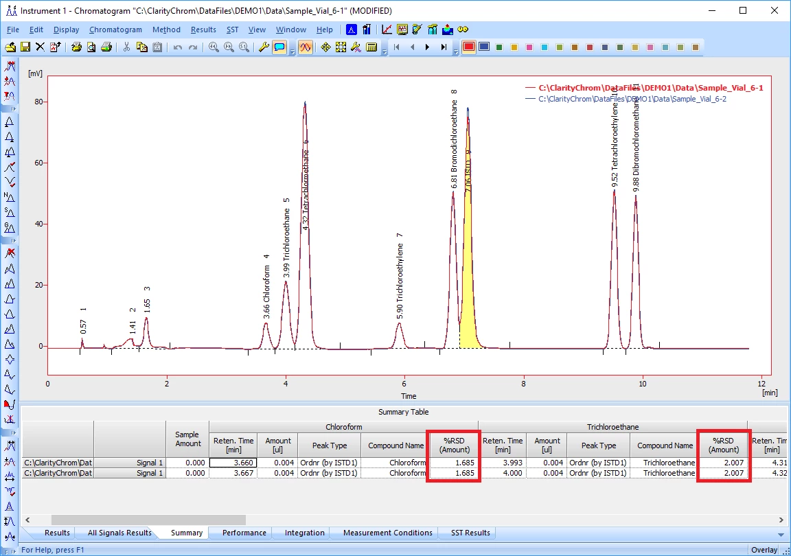
9. The new column with the calculated result is shown. The calculation is done for the whole column that means for all chromatograms; in every line the same value is shown.
Finally, it feels like a workaround. To use the SST extension for this job is easier to set. Additionally, the SST result allows setting limits, shows the value range and show “pass” or “failed” according to the set limits.
ClarityChromPrep, the preparative software from KNAUER, based on ClarityChrom, is discontinued. The latest version is 7.2.0. But the preparative functionality, implemented exclusively by KNAUER, is still available. For ClarityChrom now a new control module, the Knauer FRC control module, is available from version 7.4.1. It enables the full preparative functionality, known from ClarityChromPrep, in ClarityChrom. Order the upgrade, KNAUER article number A1687, to receive the latest version of our software. Along with the installation media you will receive a new user code that enables the Knauer FRC control module for ClarityChrom on your dongle. Please always send your ClarityChromPrep serial number or dongle number with your order.
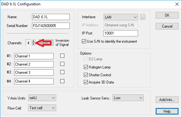
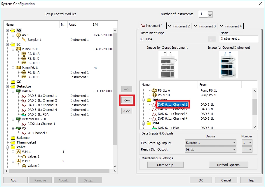
The number of channels of a PDA or MWD can be setup in the detector configuration. Only the channels, selected in the configuration, can later be used in the method setup.
The detector configuration windows allows enabling or disabling channels via the small Channel arrow keys. How many channels can be enabled depends on the detector type.
If the Channel arrow keys are not accessible, the detector has been already added to an instrument. To change the number of channels, remove the detector from the instrument by moving it from the instrument to the “Setup Control Modules” column on the left side of the ClarityChrom configuration window. Now the Channel arrow keys are accessible. Enable the desired number of detector channels and add the detector to the instrument again.
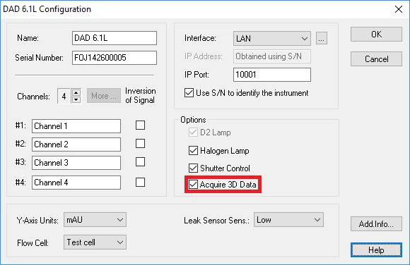
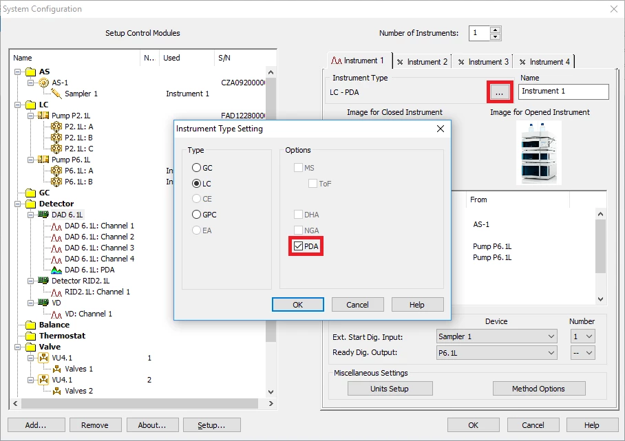
If a PDA is configured, the 3D data acquisition is enabled by default. Using a detector with enabled 3D data acquisition requires a PDA license extension. By default, extensions are not enabled in the instrument type settings. Only if the appropriate extension is enabled, the device can be added to the instrument. To enable the PDA extension, click on the <…> button in the Instrument Type section to open the Instrument Type setup. Enable the check box for PDA and click <OK> to store the setting. If the PDA license extension is available, the setup can be stored; otherwise an error message appears. In case the PDA extension is not available, you need to purchase this extension.
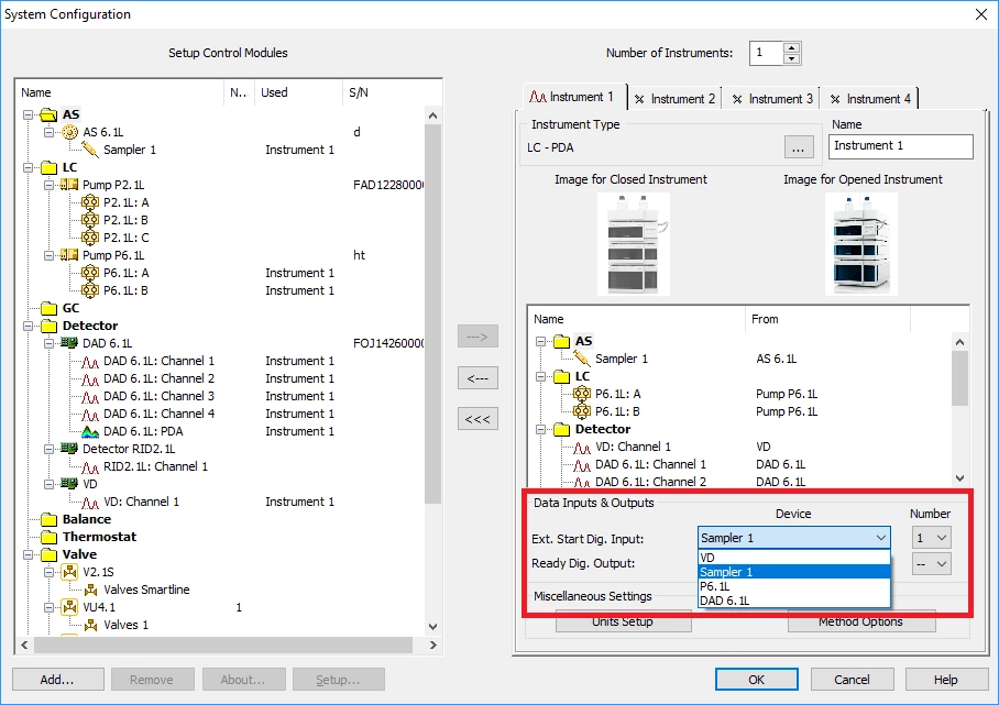
For a synchronous start of all devices, in ClarityChrom a device must be defined to receive the trigger/start input signal. The device must be defined in the system configuration. In the lower right corner of the configuration window the section “Data Inputs & Outputs” can be found. In “Ext. Start Dig. Input:” select as “Device” the device, which is connected to the injection system (either to manual injection valve or autosampler). The trigger cable must be connected to the Start and Ground pins of the selected device. If an autosampler is used, you also can select the sampler in “Device”. In this case, no trigger cable must be connected; the software will detect via the status of the autosampler if an injection is made and start the run. As “Number” always select “1”; otherwise the trigger/start signal will not be detected.
If you use an A/D converter, as the KNAUER IFU 2.1, for the trigger/start input signal, also numbers 2, 3 and 4 are selectable. Select the number that corresponds with the channel number you have connected with the trigger cable. The Start input of the AZURA valve unifier VU 4.1 is not supported in ClarityChrom. If the VU 4.1 or the Virtual Detector is selected as device in “Ext. Start Dig. Input:”, runs in a sequence will be started automatically if all devices report a “Ready” status.
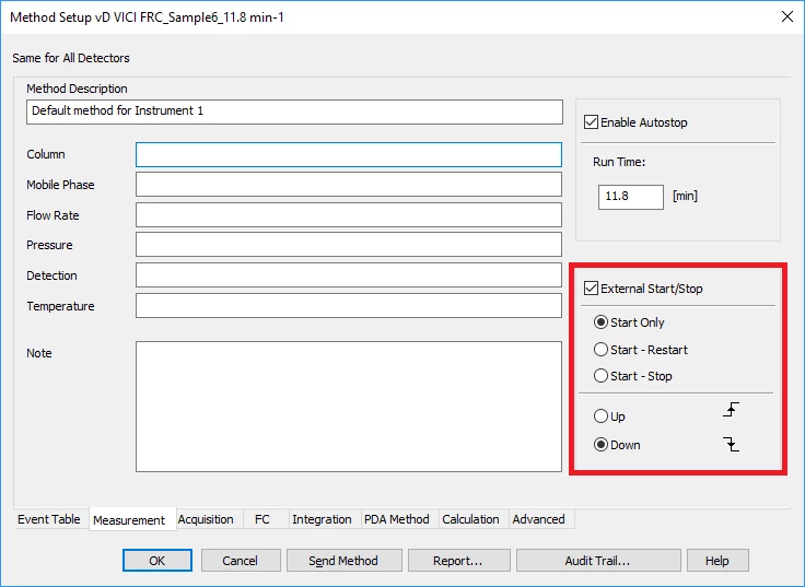
In the method setup, on tab “Measurement”, the option “External Start/Stop” must be enabled for detecting the trigger/start input signal.
Trouble Shooting
1. In ClarityChrom configuration, the correct device must be selected in “Ext. Start Dig. Input:”; “Number” must either be set to “1” or, in case of an A/D converter, to the number, corresponding to the used channel for trigger/start input signal.
2. In the method setup, tab Measurement, the option “External Start/Stop” must be enabled. Additionally, only start options “Start only” and “Down” must be enabled, other options may cause problems.
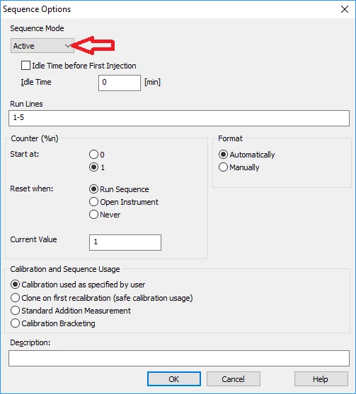
3. If a sequence is used, the sequence mode “Active” must be selected. This setting can be found in Sequence > Options.
4. In case a trigger cable is connected, the cable must be connected to Start and Ground of the selected device. For some devices, e.g. autosampler Spark Marathon, the cables for Start and Ground are different; make sure the correct cables are connected to Start pin and Ground pin.
5. The Start pin of the AZURA valve unifier VU 4.1 is not supported in ClarityChrom.
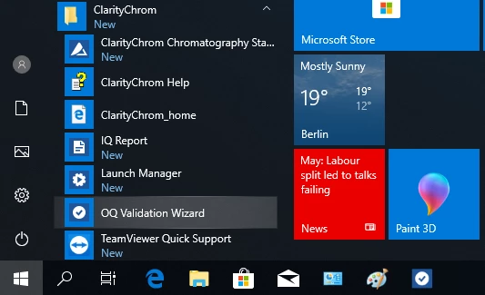
ClarityChrom 8.1 comes with integrated IQ and OQ procedures. Both can run without any additional hardware. The OQ requires the ClarityChrom SST extension for the proper calculation of the test results.
ClarityChrom IQ
The IQ checks for a list of installed files via check sum, whether the current state of the files are as installed or if it is changed. The results will be shown in a report.
1. To start IQ procedure, click Start > ClarityChrom > IQ Report.
2. After a few seconds, the Installation Qualification Report will appear. In the header some general information, e.g. the date and time of the qualification run, license serial number, installed version of ClarityChrom and configured acquisition and hardware devices will be listed. In a table below, the checked files with their installation path, version, size and file date and the qualification status are listed. Files that found as expected (installed) are shown with status “passed”. Files with a non-matching check sum will be marked as “Failed: bad checksum”. Unexpectedly found files will be listed with status “Failed: does not have record in certification file”. The IQ report can be printed.
———————–
ClarityChrom OQ
The automated OQ procedure runs several virtual acquisition procedures, integrates the acquired chromatograms and compares the found results with the expected results. Finally 3 reports will be created. For the calculation the ClarityChrom SST extension is required.
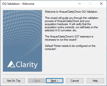
1. To start the OQ validation wizard, click Start > ClarityChrom > OQ Validation Wizard.
2. On the Welcome screen. click <OK>.
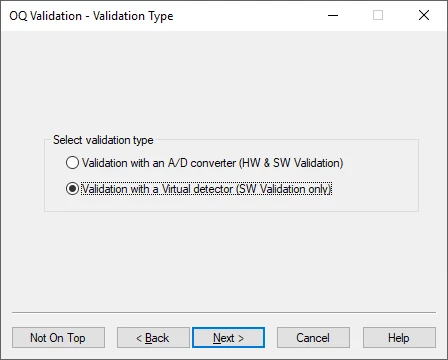
3. On the Validation Type screen, select “Validation with Virtual detector (SW Validation only). Click <Next>.
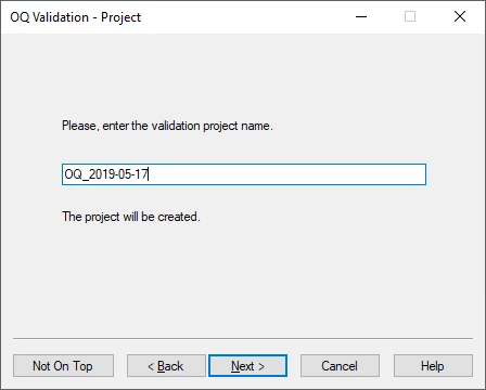
4. ClarityChrom will create a separate project in which the files will be stored. Enter a name for the project and click <Next>.
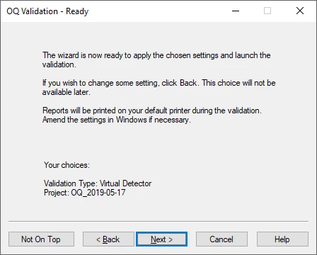
5. The Ready screen shows your choices. Click <Next> for proceeding with the qualification.
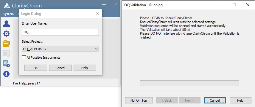
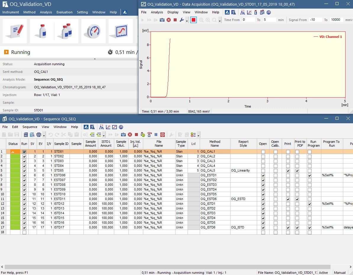
6. The ClarityChrom instrument login dialog window appears, If you click <OK>, the qualification procedure starts. The process runs fully automated and requires about 50 minutes. Within this time, you cannot run the ClarityChrom station for any other work.
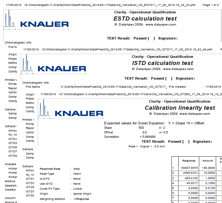
7. If the OQ is finished, 3 reports for ESTD calculation test, ISTD calculation test and Calibration linearity test can be printed. You need to check the found results in the ClarityChrom chromatogram window and mark manually in the reports, if the results are OK or not.
This is our original “workhorse” version 5 of PurityChrom. We now also offer a completely re-written version 6 (PurityChrom 6), which offers new features like multi-system configuration, animated flowpath visualization, facilitated method creation, and the “cherry on the top”: GAMP 5 as well as 21 CFR part 11 compliance.
However, PurityChrom 5 is still available because the new version 6 does not support the full range of devices, e.g. autosampler, DAD or column thermostat are not yet supported, but the range of supported devices will be enhanced continously.
PurityChrom® is a preparative chromatography software especially designed for the area of bio purification and FPLC. It includes intuitive data evaluation with peak recognition and integration.
Due to its high flexibility, methods can be developed according to specific demands. Although pre-set for volume-based operation, you have the freedom of creating methods also based on coloumn volume or time. There is also a possibility to pause a method during the run, providing you with complete control over your chromatography process. For fractionation, PurityChrom offers advanced options including logical combinations of detection criteria. Fractionation can be carried out using a fractionation valve as well as a fraction collector.
PurityChrom supports the modular concept of KNAUER AZURA and thus comes as an expandable solution. Check the different product options.
PurityChrom 5 Tutorials
Get an impression of the look-and-feel of PurityChrom. In our short video tutorials you can see how to start the software, set up your system, or write a method.
PurityChrom 6 is the next generation of KNAUER`s purification software.
It is designed to adress all separation tasks in biopurification and preparative HPLC. PurityChrom 6’s animated flowpath visualization improves usability and method writing whilst providing intelligent fraction collection and the ability to configure several different systems in one program.
The cherry on top? The software also meets the standards of GAMP 5 and 21 CFR part 11.
PurityChrom 6 Tutorials
Get an impression of the look-and-feel of PurityChrom 6 and simply find instructions to get starteted with the new PurityChrom 6. In our short video tutorials you can see how to start the software, set up your system, or write a method.
The hand-held Mobile Control (Chrom) allows a complete overview of all devices of the AZURA systems on one screen. Remotely check important parameters or control and monitor devices. The touch screen interface facilitates navigation using just your fingers. Choose Mobile Control as a basic, easy-to-use and cost-effective software solution!
ClarityChrom is an easy-to-use chromatography data system for workstations. The optional GC-, MS and KNAUER FRC control modules and extensions for PDA, SST, and SEC/GPC allow using the software for a wide range of applications.
The KNAUER FRC control module enables the drivers for several fraction collectors and supports the peak fractionation by time, level and/or slope. The manual fraction control, the option to use the KNAUER electrical valves for fractionation and, with a supported mass spectrometer, mass-triggered fractionation offers an astonishing flexibility. The rack view gives detailed information about all collected fractions and direct links to open the matching chromatograms. The functionality corresponds to the former ClarityChromPrep; this separate preparative software is discontinued.
ClarityChrom Software Tutorials
A series of short instructional videos how to work effectively with Clarity chromatography data system.
All used solvents should be of the highest quality. HPLC grade or MS grade solvents are suitable because they do not contain impurities that might lead to contamination peaks. Make sure that the used water for mobile phases is also of highest purity. It should be additionally purified and not only deionized.
Mobile phases should be filtrated if necessary. They can be filtered through a 0.45 µm filter. This removes any particulate matter that may cause blockages. Filtering HPLC solvents will benefit both your chromatography and HPLC system. Pump plungers, seals and check valves will perform better, and lifetimes will be maximized.
Before pumping the freshly prepared mobile phase through the HPLC system, it should be thoroughly degassed to remove all dissolved gasses. Offline degassing can be performed via:
Bubbling with helium
Sonication
Vacuum filtration
Additionally, modern HPLC pumps have an integrated module for online degassing. If the mobile phase is not or incomplete degassed, air bubbles can form in the system resulting in problems like for example system instability or spurious baseline peaks.
Not all solvents are miscible. If you are unsure about the miscibility, then try mixing in a vessel before using the HPLC instrument. The shown miscibility chart is also a helpful tool. (white = miscible, black = immiscible) Example: acetonitrile and water are miscible, but mixing acetonitrile with hexane will not work.
Before performing any solvent change, make sure the actual used solvent in the system is compatible with the new solvent. If the miscibility is not given, an additional flushing procedure with an appropriate solubilizer is necessary. Removal of the column from the system before flushing is recommended.
Example: if you want to flush your system from acetontrile:water to heptane, you need an additional flushing step inbetween with for example isopropanol.
All prepared buffer solutions should be clear, homogeneous, and free from non-dissolved particles. They should be prepared freshly at the day of use. Adjusted pH values should be checked to avoid an effect on chromatography. If buffer solutions should be stored, keep in mind that they have limited lifetime.
Do not use highly basic or acidic solvents unless your HPLC system and applied column are able to withstand these properties. Seals and other wetted parts can be damaged by extreme pH conditions. Highly aqueous mobile phase can only be used with certain columns. A high water content in the mobile phase can promote bacterial growth. To prevent this, the system/column needs to be flushed with organic solvent in regular intervals.
After switching on the devices, they need some warm up time. Lamps of UV or DAD detectors need to be warmed up for approximately 30 minutes to ensure a stable baseline. The flow cells of RI detectors additionally need to be flushed with the solvent to avoid air bubbles and to adjust the zero glass. Furthermore, the HPLC column also needs time to equilibrate properly.
The equlibration time of a column is dependent on the column dimension/column void volume and used flowrate. A column in a dimension 250 x 4 mm ID has a column void volume of aproximately 2.8 mL. So it takes about 14 minutes at flowrate of 1 mL/min to flush the column with five times the column volume.
Not every compound can be detected with a UV detector. If you are not sure if your analyte can be detected with UV, the attached list of chromophore systems will help you.
Every solvent has its specific absorbance cutoff wavelength. Below this wavelength the solvent itself absorbs the light. When choosing a solvent be aware of its cutoff and where your desired analytes will absorb. If the wavelengths are close, choose a different solvent. The list below displays the UV cutoff wavelengths of common solvents.
Substances tagged with GHS labels should only be weighed in under an extractor hood. It is always important to keep the weighing place clean to avoid contaminations. Other colleagues should be informed about special exposures, for example when you are working with CMR (carcinogenic, mutagenic, reproductive toxic) substances.
It is also necessary to keep the weighing range of the scale in mind. If the weighing range is for example 10 mg to 120 g, it is not reasonable to weigh amounts below 10 mg because of the error of the scale.
In most laboratories wearing safety glasses is mandatory. The requirements for personal eye protection equipment is described in DIN EN 166. In special cases the use of a goggle or even a complete face protection shield can be necessary.
For every exposure with chemicals, safety gloves should be worn. Dependant on the chemical properties of the used substance, the appropriate glove must be chosen. Therefore, most vendors of safety gloves provide tables with permeability times for certain substances. Furthermore the gloves are classified in scale numbers/permeation levels from 1 to 6. These are fixed in DIN EN 374.
Example: a nitrile glove (thickness ~ 0.14 mm) is suitable for working with phosphoric acid (permeation level 6, breakthrough time > 480 min) but only provides limited protection for ethanol (permeation level 1, breakthrough time 20 min) and no protection for methanol (permeation level 0, breakthrough time 7 min). The appropriate glove for your application should at least provide protection at permeation level 2 (breakthrough time > 30 min).
No! Gloves are only for the direct contact with chemicals and must not be worn when opening doors or using the computer keypad, for example. This might cause contaminations and possible exposition of used chemicals to other colleagues.
Some gloves are for single use only and should be thrown away directly after using them or rather when a contact with the chemical has happened considering the permeation level. Other gloves are for multiple use and need to be cleaned after usage. Nevertheless, they should be replaced within a predefined period. This also depends on how often they were used.